This guide explains the Extech EX900, a professional clamp meter designed for measuring electrical current and a broad range of related parameters. The article examines its measurement functions, operating principles, safety considerations, practical applications, limitations, and maintenance requirements. It also provides an objective framework for comparing the instrument with other meters, selecting suitable accessories, and interpreting readings responsibly in residential, commercial, and industrial environments.
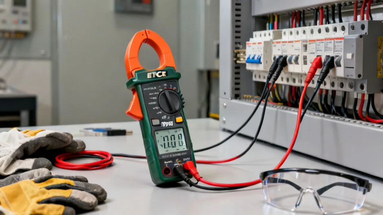
The Extech EX900 is a multifunction clamp meter intended for electrical troubleshooting, maintenance, commissioning, and general measurement work. Its defining feature is the ability to measure current by clamping around a conductor rather than disconnecting the circuit and placing the meter in series. That approach can improve workflow and reduce unnecessary circuit interruption, provided the user follows the instrument’s safety instructions and confirms that the conductor, measurement category, and current level are appropriate.
For professionals evaluating the Extech EX900, the most important considerations are not simply the number of functions printed on the front panel. Measurement category, maximum current range, conductor position inside the jaw, lead condition, battery status, environmental conditions, and user competence all influence whether a reading is meaningful. A clamp meter is a practical diagnostic tool, but it is not a substitute for a planned electrical safety procedure.
The model is generally associated with AC and DC current measurement and with common multimeter functions such as voltage, resistance, continuity, capacitance, frequency, duty cycle, diode testing, and temperature measurement. Exact specifications, included accessories, supported temperature-probe types, and regional packaging should always be confirmed in the current manufacturer documentation or through an authorized supplier. Product versions and supplied kits can vary by market.
A useful way to think about the EX900 is as a field instrument for gathering several related pieces of evidence. A technician can measure current without opening a circuit, verify voltage with test leads, inspect a disconnected component with resistance or continuity functions, and examine selected electrical characteristics such as frequency or duty cycle. These functions can reduce the number of instruments carried to a job, although specialized applications may still require dedicated testers.
A conventional multimeter measures current by becoming part of the circuit. The circuit must be opened, the leads must be connected correctly, and the meter’s current input must be protected against misuse. A clamp meter uses a hinged jaw to sense the magnetic field around a conductor. This allows the technician to assess current without physically breaking the circuit in many situations.
The Extech EX900 combines that current-sensing function with the operating format of a digital multimeter. Depending on the selected mode, the instrument may be used to assess voltage between two points, resistance across a de-energized component, continuity through a conductor, capacitance in a disconnected component, frequency, duty cycle, diode forward voltage, or temperature with a compatible probe. These capabilities make the instrument relevant to several maintenance tasks rather than limiting it to current checks alone.
Its usefulness is especially apparent during first-line fault finding. A technician may begin by checking whether a supply voltage is present, move to current measurement to identify an overloaded or non-operating circuit, and then use resistance or continuity functions after isolating the equipment. The same meter can therefore support a sequence of related observations. However, every transition between functions requires deliberate control selection and appropriate lead placement.
The instrument may also be useful during preventive maintenance. Current measurements can be compared with previous readings, equipment nameplate information, or readings from similar machines. A change over time may indicate a developing mechanical or electrical issue, although current alone rarely identifies the exact cause. Preventive maintenance is most effective when meter readings are combined with inspection, temperature observations, vibration information, operating history, and manufacturer recommendations.
| Function | Typical purpose | Important condition |
|---|---|---|
| AC current | Assess current flowing through a single alternating-current conductor | Place only the intended conductor inside the jaw |
| DC current | Check current in battery systems, vehicle circuits, control systems, and other direct-current applications | Observe zero adjustment and polarity-related indications where applicable |
| AC or DC voltage | Verify supply presence, control voltage, battery voltage, or potential difference | Use leads in the correct terminals and select the correct mode |
| Resistance | Evaluate resistors, windings, conductors, and disconnected components | De-energize and discharge the circuit before connecting the leads |
| Continuity | Identify low-resistance electrical paths | Do not use continuity mode on an energized circuit |
| Capacitance | Estimate the capacitance of an isolated component | Discharge capacitors and allow the reading to stabilize |
| Frequency and duty cycle | Examine periodic electrical signals and switching behavior | Confirm that the signal amplitude and waveform are suitable for the selected input |
| Diode test | Check forward-bias behavior of a diode or semiconductor junction | Test only on an isolated, de-energized component |
| Temperature | Observe temperature at a contact point or through a compatible probe | Use a probe rated for the expected temperature and application |
The table describes practical roles rather than a replacement for the model’s technical specification sheet. Resolution, accuracy, input impedance, response characteristics, overload protection, and operating limits determine how each mode should be used. Professionals should treat those details as selection criteria, especially when measurements will inform repairs, compliance decisions, or equipment commissioning.
The presence of multiple functions does not mean every function has identical performance. A meter may be especially useful for general current and voltage checks while being less suitable for precision capacitance measurements, very low-current work, rapidly changing signals, or complex power-electronic waveforms. The operating manual normally explains the conditions that apply to each mode, including input limits, connection methods, and expected response behavior.
Current measurement is the reason many technicians choose the Extech EX900 rather than a basic handheld multimeter. In clamp mode, the jaw surrounds a conductor and detects the magnetic field generated by the current. The conductor must pass through the central area of the jaw as far as practical. Keeping the conductor away from the hinge and jaw edges can help produce more consistent results.
Only one current-carrying conductor should normally be enclosed when measuring load current. If both the outgoing and returning conductors of a single-phase circuit are placed inside the jaw, their magnetic fields may oppose one another. The display can then show a very small value even though the circuit is energized. This is a common procedural error, not necessarily a defect in the meter.
When measuring DC current, the user may need to zero or null the display before clamping around the conductor, depending on the operating procedure specified by the manufacturer. Residual magnetic effects, jaw position, nearby conductors, and external magnetic fields can influence the indication. If a DC reading appears unstable or inconsistent, remove the jaw from the conductor, verify the selected mode, repeat the zero procedure, and compare the result with an independent measurement where safety permits.
Current readings should be interpreted in context. A motor may draw a higher current during startup than during normal operation. A power supply may have a non-sinusoidal input current caused by electronic switching. A battery system may exhibit different current behavior during charging, standby, and peak load. One isolated reading does not automatically establish that equipment is defective or operating correctly.
For three-phase equipment, phase-to-phase comparison can be informative. If similar phases carry substantially different currents under a balanced load, the difference may justify further investigation. Possible causes include supply imbalance, a loose connection, a damaged winding, unequal mechanical loading, or a measurement error. The phases should be measured under the same operating conditions, with the clamp positioned consistently and the equipment allowed to reach a comparable state.
When measuring a large conductor, the operator should not force the jaw over insulation, cable supports, or adjacent hardware. If access is restricted, the correct answer may be to use an approved flexible probe, shut down the equipment, or redesign the test procedure. Convenience should never determine whether a conductor is approached in an unsafe position.
Voltage measurement is performed with the test leads rather than the clamp jaw. Before connecting the leads, the operator should identify the expected voltage, select the correct function, inspect the lead insulation, and verify that the leads are inserted into the appropriate terminals. The black lead is commonly connected to the common terminal, while the red lead is moved to the voltage or specialized input required by the selected function. The markings on the instrument and manual take precedence over general practice.
A frequent hazard occurs when the red lead remains in a current input while the user attempts to measure voltage. Depending on the instrument and circuit, this can create a short circuit, damage the meter, or cause arc flash. A disciplined operator returns the lead to the common voltage terminal immediately after a current-related measurement and checks the selector before touching a live circuit.
Voltage readings should be made using a stable reference point and suitable contact pressure. Avoid holding exposed metal probe tips with the fingers. Where possible, use probes with guards, insulated alligator clips, or accessories designed for the environment. In crowded panels, the physical arrangement of the probes is as important as the electrical range selected on the display.
It is good practice to use the “live-dead-live” verification method where the site procedure requires it. This generally involves checking the tester on a known energized source, testing the circuit under investigation, and then checking the tester again on the known source. The procedure helps identify a failed meter, depleted battery, damaged lead, or incorrect function selection. The exact method must follow the employer’s safety program and applicable regulations.
When checking a control circuit, remember that a voltage reading can exist even when the circuit cannot deliver useful current. A high-impedance meter may display induced or “ghost” voltage through capacitive coupling. If the distinction between real and induced voltage matters, use an approved method or instrument designed for that diagnostic question. Do not assume that every displayed voltage represents a robust power source.
Measurement category, often identified by CAT designations, describes the type of transient environment in which test equipment is intended to be used. CAT ratings are not interchangeable with a voltage number alone. A device marked for a particular category and voltage should be used only within the limits stated by the manufacturer. Distribution panels, branch circuits, fixed installations, and equipment supplied from an industrial source can expose instruments to different transient conditions.
Before using the Extech EX900, inspect the housing, jaw, rotary selector, display, input terminals, probe bodies, and lead insulation. Do not use a meter with cracked insulation, loose components, damaged jaw alignment, or signs of overheating. Test the instrument on a known, suitable source before and after a critical measurement when the work procedure allows it. This confirms that the display, leads, and selected function are behaving as expected.
Personal protective equipment should be selected according to the hazard assessment, not merely because a clamp meter is being used. Depending on the installation, requirements may include eye protection, insulated gloves, flame-resistant clothing, hearing protection, or arc-rated equipment. Site procedures, applicable electrical codes, lockout and tagout rules, and employer requirements remain essential.
The safest measurement is often the one that can be made with the circuit de-energized. For energized work, only trained and authorized personnel should proceed. The Extech EX900 can assist with diagnosis, but it cannot remove the hazards associated with exposed energized conductors, unexpected backfeed, stored energy, short circuits, or arc flash.
Never rely only on the position of a disconnect switch. A circuit may remain energized because of a second supply, generator, inverter, control transformer, photovoltaic source, battery bank, or incorrect wiring. Isolation must be verified using the procedure established for the installation. Stored energy in capacitors and rotating machinery can also remain hazardous after a source has been disconnected.
Identify whether the task involves AC current, DC current, voltage, resistance, continuity, capacitance, frequency, duty cycle, diode behavior, or temperature. Clarify whether the circuit is expected to be energized and determine the maximum possible value before selecting a range.
Examine the enclosure, access points, conductor size, available clearance, moisture, dust, heat, and nearby magnetic sources. Confirm that the jaw can close fully around the intended conductor and that the meter’s category and voltage limits are suitable for the installation.
Check the meter body, jaw faces, selector, display, terminals, probes, and lead insulation. Replace damaged accessories. Confirm that the battery has sufficient charge and that the display does not show a low-battery indication that could affect operation or readability.
When the value is unknown, begin with the highest suitable range or an automatic range if the manufacturer’s operating instructions permit it. A conservative starting point reduces the chance of exceeding the selected range and gives the operator time to assess the circuit behavior.
Open the jaw, place one conductor inside it, close the jaw completely, and keep the conductor centered. Do not clamp around an entire multi-conductor cable when the opposing fields would cancel. Read the display only after the indication has stabilized, and be alert for changing loads or inrush conditions.
Connect the common lead and voltage lead to the correct terminals. Touch the probes to the intended points without allowing the tips to bridge adjacent conductors. Observe polarity and range indications, and remove the probes in a controlled manner after recording the measurement.
For resistance, continuity, capacitance, and diode tests, turn off the circuit, apply the site’s isolation procedure, and verify the absence of voltage with an appropriate method. Discharge capacitors and consider whether parallel components could distort the reading. A circuit can appear de-energized while retaining stored energy.
Document the function, range, approximate environmental conditions, test points, load state, and observed reading. Good records help distinguish a temporary operating condition from a repeatable fault. In industrial maintenance, the time and operating state of the equipment may be as important as the numerical value.
Remove the probes, switch off the instrument when appropriate, return the leads to their standard storage position, and clean the meter according to the manufacturer’s guidance. Store it in a dry protective case away from excessive heat, corrosive chemicals, and sharp tools.
In residential work, a clamp meter may help assess the current drawn by appliances, pumps, heating equipment, or selected branch-circuit conductors. It may also help a qualified technician compare normal load behavior with a suspected overload. The main challenge is access: residential cables often contain multiple conductors inside one outer sheath, so clamping around the complete cable may not provide the intended result.
Residential users should not open energized panels or remove protective covers without the necessary training and authorization. A clamp meter’s compact format can make electrical work look simple, but the hazards remain serious. For homeowners, an electrician is usually the appropriate person to perform measurements inside distribution equipment.
Commercial maintenance teams may use the Extech EX900 for panel surveys, HVAC troubleshooting, lighting circuits, pumps, fans, control cabinets, and small motor systems. Comparing current among similar phases or equivalent loads can help identify abnormal conditions, but readings should be interpreted alongside voltage, equipment nameplate data, operating temperature, vibration, and maintenance history.
In commercial environments, access control and documentation are particularly important. Panels may contain multiple sources, automatic transfer equipment, variable-frequency drives, or power-factor correction components. A current measurement should be planned around the system’s operating state and the facility’s electrical safety program.
Industrial applications may include machinery, conveyors, motor starters, battery-backed control circuits, instrumentation cabinets, and production equipment. The instrument can support routine checks and preliminary fault isolation. Nevertheless, industrial systems often contain harmonics, switching transients, high fault energy, and complex grounding arrangements. A multifunction meter should be used within its documented capabilities and supplemented with specialized instruments when waveform analysis, insulation testing, phase rotation, power quality, or high-energy testing is required.
DC clamp measurement can be useful when examining battery charging, auxiliary loads, starter-related circuits, or control-system consumption. The current range and jaw opening must be appropriate for the conductor and expected load. The technician should also account for vehicle operating modes, sleep states, ignition status, and electronic modules that may wake intermittently.
Low-voltage solar, battery, and backup-power systems can involve substantial DC current even when the nominal voltage appears modest. DC arcs can be difficult to extinguish, and battery banks can deliver very high fault current. The EX900 should be used only where its documented category and current ratings are suitable. Technicians must account for parallel strings, charge controllers, inverters, and sources that remain active in daylight or during backup operation.
Accuracy and resolution are different concepts. Resolution describes the smallest display increment in a particular range. Accuracy describes how close the result is expected to be to the actual value under stated conditions. A display that shows several digits does not automatically guarantee a highly accurate measurement.
Clamp meters can be less accurate at very low currents than at mid-range currents, especially when the jaw is not fully closed or when the conductor is positioned near the edge. External magnetic fields may also affect the measurement. For low-current applications, a specialized low-current clamp meter or an appropriate current adapter may produce more dependable results.
Temperature can influence electronic instruments and test leads. Measuring in a hot switch room, a cold outdoor cabinet, or a humid service area may require attention to the operating conditions specified in the manual. Condensation is a particular concern because moisture can compromise insulation and produce unstable readings.
Where a decision has significant safety, regulatory, or financial consequences, a second instrument or a calibrated reference may be appropriate. Cross-checking does not mean arbitrarily choosing the reading that appears convenient. It means confirming that both instruments are suitable, correctly connected, and used under comparable conditions.
When a reading fluctuates, the fluctuation itself may be useful information. It may reflect a variable-speed drive, thermostat, compressor cycle, relay operation, intermittent connection, or electronic control sequence. Instead of immediately assuming the meter is defective, observe whether the displayed change corresponds with an audible, mechanical, or visible change in the equipment.
Another source of error is the assumption that the conductor current is uniform over every part of a complex assembly. Busbars, parallel conductors, split-phase arrangements, and conductors routed close together can create magnetic fields that do not behave like a simple isolated wire. If the measurement is unexpectedly different from the equipment’s design information, repeat the test at a more suitable point rather than forcing a conclusion from one position.
Accessories can determine whether a clamp meter is practical in a particular workspace. Test leads with finger guards help reduce accidental contact. Insulated clips can support hands-free measurements when the work procedure permits them. A temperature probe must match the meter’s supported connector and measurement range. A protective case can reduce damage during transport between workshops, vehicles, and plant rooms.
For measurements in narrow cabinets, jaw access may be the limiting factor. Flexible current probes or slim clamp accessories can reach conductors that a conventional jaw cannot. These accessories should be selected for compatible ratings and connectors rather than treated as universal attachments.
Replacement leads and probes should meet the required safety category and voltage rating. A technically compatible connector is not enough if the accessory’s insulation or transient rating is unsuitable. When purchasing a replacement kit, verify the manufacturer’s part information and the requirements of the work environment.
Probe length and body shape also affect ergonomics. Long, rigid probes may be useful in open equipment but awkward in confined panels. Right-angle accessories can reduce hand strain and help keep the operator’s body away from an enclosure. These considerations are secondary to electrical ratings, but they can improve control and reduce accidental movement during a measurement.
Routine care begins with cleaning. Use a soft, dry cloth unless the manufacturer specifically permits a mild cleaning solution. Keep liquids away from the terminals, selector mechanism, display seams, and jaw hinge. Do not use abrasive materials that could damage insulation or markings.
The jaw faces should remain clean and aligned. Dust, metal particles, and sticky residue can prevent complete closure. Do not force the jaw open beyond its mechanical limit. If the jaw does not close smoothly or leaves a visible gap, remove the instrument from service until it has been inspected.
Calibration intervals depend on usage, risk, quality procedures, and organizational policy. A laboratory, industrial maintenance department, or contractor may establish an annual interval, while a lower-risk user may follow a different documented schedule. The correct interval is determined by the consequences of inaccurate readings, frequency of use, environmental exposure, and prior calibration history.
Calibration should be performed by a competent service provider using traceable equipment appropriate to the meter’s functions. A calibration certificate is useful only when it identifies the instrument, standards, conditions, results, and date clearly. Calibration does not repair a damaged meter; condition assessment and functional checks remain necessary.
Remove or replace the battery according to the storage instructions if the meter will remain unused for an extended period. Battery leakage can damage internal contacts and circuit boards. Store the instrument in a moderate, dry environment, away from direct sunlight, excessive vibration, and chemicals that may attack plastics or insulation.
A pre-use functional check should be part of routine maintenance. Verify that the display segments appear normally at startup, that the selector responds correctly, that the jaw opens and closes without binding, and that the leads fit securely in the terminals. If the meter has been dropped, exposed to an overvoltage event, or subjected to unusual heat, it should be inspected even if it still produces numbers.
Buyers should begin with the work rather than the product name. List the highest expected voltage and current, whether AC and DC measurements are both required, the conductor diameter, the measurement category, the need for temperature or capacitance testing, and the expected working environment. This list creates a practical specification against which the Extech EX900 can be assessed.
Next, review the official data sheet and manual. Confirm the current ranges, voltage limits, accuracy statements, display behavior, input protection, jaw opening, operating temperature, battery type, dimensions, and included accessories. Pay particular attention to notes attached to each function. A function may be available but limited to a narrower range, a specific waveform, or a defined environmental condition.
Supplier reliability also matters. An established electrical test-equipment supplier should be able to identify the exact model, provide documentation, explain warranty terms, and state whether the item is new, refurbished, or previously used. Buyers should be cautious when a listing omits measurement category information, gives inconsistent specifications, or uses generic photographs that do not clearly identify the product.
Price should be considered alongside total ownership cost. Replacement leads, calibration, batteries, protective storage, shipping, taxes, and downtime can affect the long-term value of a meter. A lower purchase price is not necessarily economical if the instrument does not meet the safety category or current range required for the job.
Consider the instrument’s physical usability before committing to a purchase. A display that is easy to read in a dark cabinet, a selector that can be operated with one hand, and a jaw that fits typical conductors may save more time than an additional function that is rarely used. If multiple technicians will share the meter, common controls and clear documentation can also reduce training errors.
| Evaluation criterion | Questions for the buyer | Why it matters |
|---|---|---|
| Current type | Does the meter support the required AC, DC, or both current measurements? | Many applications require more than alternating-current measurement. |
| Maximum current | Is the expected load comfortably below the documented limit? | Operating near a limit can reduce flexibility and increase risk. |
| Jaw opening | Can the jaw fit around the conductors encountered in the field? | A meter cannot measure a conductor it cannot safely enclose. |
| Measurement category | Is the CAT and voltage rating appropriate for the installation? | Transient exposure varies between circuits and locations. |
| Low-current performance | Is the instrument suitable for the smallest current that must be detected? | Large-current capability does not guarantee sensitive low-current measurement. |
| Additional functions | Are voltage, resistance, continuity, capacitance, frequency, temperature, or diode tests needed? | Relevant functions can reduce the number of instruments required. |
| Display and controls | Can the display be read clearly and the selector operated with protective equipment? | Usability affects the quality of field measurements. |
| Service support | Are manuals, replacement accessories, calibration, and warranty support available? | Support contributes to dependable long-term use. |
The Extech EX900 should not be presented as a universal diagnostic platform. A clamp meter cannot replace an insulation resistance tester when insulation condition is the issue. It cannot replace a power-quality analyzer when the task involves harmonics, sags, swells, transients, or detailed waveform characterization. It is also not the correct instrument for every high-voltage, high-frequency, or specialized process measurement.
Current readings alone do not identify the root cause of a fault. An excessive motor current may result from mechanical overload, incorrect supply conditions, bearing problems, phase imbalance, restricted airflow, or control issues. A low current may indicate a disconnected load, a failed winding, an open contact, or simply a normal light-load condition. Diagnostic conclusions should be based on several coordinated tests.
Similarly, resistance testing can be misleading when a component remains connected to a larger circuit. Parallel paths, semiconductor junctions, relays, capacitors, and control electronics can all influence the display. Isolation and circuit knowledge are therefore essential before interpreting an ohms reading.
The meter also should not be used to make assumptions about energy consumption from a single current value. Real power depends on voltage, current, power factor, waveform, and operating time. In a motor or electronic power supply, apparent current and real energy use may differ substantially. If billing, efficiency, or power-factor analysis is the objective, use equipment intended to measure those quantities directly.
Error: The user surrounds a multi-conductor cable and sees little or no current.
Better practice: Access one current-carrying conductor where the installation design and safety procedure permit it. If individual conductors cannot be accessed, use a suitable alternative method or consult a qualified technician.
Error: The red lead remains connected to a current input while the selector is moved to voltage.
Better practice: Adopt a lead-return routine. After every current measurement, move the lead back to the standard voltage terminal before performing another task.
Error: The operator selects resistance without verifying isolation.
Better practice: De-energize, lock out when required, discharge stored energy, and verify the absence of voltage using the site-approved method.
Error: A startup peak is interpreted as the steady operating current.
Better practice: Distinguish startup, running, standby, and fault conditions. Use a suitable capture or inrush function only if the instrument provides it and the procedure is understood.
Error: The user records a steady display without considering range, position, waveform, or calibration.
Better practice: Review the conditions affecting accuracy and compare the result with expected equipment data and, when necessary, an independent reference.
Error: A voltage is measured against a convenient point that is not the circuit’s intended reference.
Better practice: Identify the circuit diagram, grounding arrangement, and test points before touching the probes. A measurement is meaningful only in relation to a defined pair of points.
Error: The range or function is changed while the probes are still attached to a live circuit.
Better practice: Remove the probes or use the approved switching procedure before changing functions. Some selections can place unexpected electrical paths across the test points.
From an industry perspective, the value of the Extech EX900 lies in structured observation. The meter is most effective when the technician asks a sequence of questions: What should the circuit be doing? What is the present operating state? Which measurement can safely test the hypothesis? Does the result agree with the equipment documentation? Can the reading be repeated?
For example, when a motor is reported to be overheating, a current measurement is only one part of the investigation. The technician may compare phase currents, verify supply voltage, inspect mechanical loading, check ventilation, review ambient temperature, and examine the motor’s operating history. If the current is elevated on one phase, the next step may involve connections, supply imbalance, winding condition, or the starter rather than replacing the motor immediately.
This method prevents a common maintenance problem: treating the meter as a decision-making device rather than as an observation device. The Extech EX900 displays electrical values. Professional judgment connects those values to circuit design, equipment behavior, and safe work practices.
A good diagnostic plan also separates confirmation from discovery. During discovery, the technician may make broad, conservative measurements to understand the circuit. During confirmation, the technician repeats a specific measurement under controlled conditions to test a suspected cause. Keeping those stages separate reduces the temptation to interpret an early, incomplete reading as a final diagnosis.
For repeat maintenance, record keeping improves the usefulness of measurements. A useful record may include the asset identification, circuit designation, date, technician, instrument model, calibration status, test function, range, conductor or test points, load condition, ambient conditions, and result. Photographs may help document probe position when site policy allows them.
Trend records can reveal gradual changes that a single inspection misses. A pump motor whose current rises over several inspections may be experiencing increasing mechanical resistance or process loading. A battery system whose standby current changes may warrant a closer examination of connected equipment. Trends should not be interpreted without considering changes in operating conditions.
When measurements are used in regulated or quality-controlled work, follow the organization’s documentation and retention requirements. The instrument’s manual, the relevant electrical code, and the employer’s procedures should take priority over informal measurement habits.
Record units as well as numerical values. “12” is ambiguous without knowing whether the result is volts, amps, ohms, degrees, hertz, or another unit. Also record whether the value was AC or DC and whether it represented a peak, startup condition, steady value, or average indication. These details make a maintenance record useful to someone who was not present during the test.
| Condition | Potential effect | Recommended response |
|---|---|---|
| High temperature | May influence instrument performance, battery life, and operator safety | Work within the documented operating range and allow the instrument to stabilize when required |
| Humidity or condensation | Can reduce insulation confidence and produce unstable readings | Keep the instrument dry and do not measure until unsafe moisture has been addressed |
| Dust or metal particles | May obstruct jaw closure or contaminate terminals | Inspect and clean according to the manufacturer’s instructions |
| Strong electromagnetic fields | Can influence low-level or clamp measurements | Reposition the instrument and compare readings where practical |
| Restricted access | May force awkward probe or jaw positioning | Use approved accessories or change the measurement plan; do not compromise safe body position |
| Changing load | Produces readings that vary with equipment operation | Record the operating state and repeat measurements under comparable conditions |
Noise, vibration, and poor lighting can affect the human side of measurement even when the meter itself is operating normally. If the operator cannot see the display clearly, maintain stable probe contact, or keep a safe stance, the task should be paused and the conditions improved. A measurement taken under poor physical control is not made reliable simply by recording more decimal places.
The instrument is best suited to trained electricians, maintenance technicians, HVAC professionals, facility engineers, controls personnel, and technically competent users working within an established safety procedure. Training should cover electrical theory, measurement-category concepts, test-lead management, isolation procedures, arc-flash awareness where applicable, and the specific equipment being tested.
It may be appropriate for educational environments when supervised by a qualified instructor. Students should begin with de-energized circuits and controlled training boards before progressing to live measurements. The presence of a digital display should never be treated as evidence that a measurement is safe to perform.
For users who need only occasional low-risk checks, a simpler instrument may be sufficient. Conversely, professionals working with advanced drives, high-energy distribution, power-quality issues, or precision laboratory measurements may require additional equipment. The Extech EX900 should be selected because its documented capabilities match the task.
Employers should also consider whether users understand the difference between an energized measurement and a zero-energy verification. A clamp reading may be possible without exposing a conductor directly, but the surrounding installation can still contain dangerous voltage. Training should include approach boundaries, safe body positioning, control of loose clothing and tools, and procedures for unexpected readings.
The Extech EX900 is a multifunction clamp meter used for electrical measurement and troubleshooting. It is associated with AC and DC current measurement through its clamp jaw and with several conventional multimeter functions through test leads. The exact functions, limits, and accessories should be confirmed in the current manufacturer documentation.
The model is generally designed for both alternating-current and direct-current clamp measurement. Users should select the correct mode, observe the specified range, and follow any zeroing or polarity instructions for DC measurement. The applicable technical limits should be verified before use.
Yes, the Extech EX900 is generally used as a digital multimeter for AC and DC voltage measurement in addition to clamp-current testing. Voltage measurements require correct lead placement, function selection, suitable category rating, and safe access to the test points.
Usually, that will not provide the intended result when the cable contains both outgoing and returning conductors. Their magnetic fields can cancel. To measure load current with a clamp, place one current-carrying conductor inside the jaw, but do so only when safe access is available and the work is performed by an appropriately trained person.
It can support preliminary motor troubleshooting by measuring current and voltage and, where appropriate, checking continuity or resistance on isolated components. It does not by itself diagnose every motor fault. Mechanical condition, phase balance, insulation, controls, load, and operating temperature may require additional tests.
The model is commonly associated with capacitance measurement, but the component must be isolated and discharged before testing. A reading may be affected by parallel circuitry or a component that has not fully discharged. Always follow the manual’s connection and safety instructions.
Turn off and isolate the circuit, verify that no hazardous voltage is present, select continuity mode, and connect the probes across the intended path. The audible indication, where provided, signals a low-resistance condition according to the meter’s threshold; it does not prove that a circuit is suitable for its intended load.
Possible causes include clamping around multiple conductors, an incompletely closed jaw, off-center conductor placement, nearby magnetic fields, an incorrect AC/DC mode, a changing load, or a low current outside the most suitable range. Repeat the measurement methodically and compare it with the circuit’s expected behavior.
There is no single interval suitable for every user. The appropriate schedule depends on risk, frequency of use, environmental exposure, quality requirements, and previous calibration results. Organizations should follow their documented procedure and use a competent calibration provider when measurement traceability is required.
Check the exact model designation, current and voltage limits, measurement category, jaw opening, functions, accuracy information, operating environment, included accessories, warranty, documentation, and supplier support. Also consider the cost and availability of replacement leads, batteries, protective storage, and calibration.
Suitability depends on the documented voltage and measurement-category ratings, the installation, the accessories, and the work procedure. Never infer suitability from the word “clamp” or from a general voltage number. High-energy systems require trained personnel, appropriate protective measures, and equipment specifically rated for the task.
No. A clamp meter can provide useful current and voltage observations, but a power-quality analyzer is designed for more detailed evaluation of harmonics, transients, waveform behavior, and other supply characteristics. Choose the instrument according to the diagnostic question.
Changing resistance can result from poor probe contact, a component that is still connected to other circuitry, a capacitor charging, movement in a cable or connector, or an unstable circuit condition. Check isolation, improve contact, allow the display to settle, and compare the result with the expected component behavior.
Only if the individual conductor can be accessed safely. Clamping around the complete cord usually surrounds both supply and return conductors, causing cancellation. Do not cut, modify, or separate a cord as an improvised measurement method. Use an approved adapter or have the work completed by a qualified person.
The Extech EX900 is best understood as a versatile field measurement instrument rather than a complete electrical diagnostic system. Its combination of clamp-based AC/DC current measurement and multimeter functions can make routine troubleshooting more efficient, particularly when technicians need to move between current, voltage, resistance, continuity, and related checks.
Its performance depends on correct technique. One conductor must generally be enclosed for current measurement, voltage leads must be returned to the proper terminals, de-energization is required for resistance-based tests, and measurement-category limits must match the installation. Jaw position, waveform, environmental conditions, calibration, and equipment operating state all influence the quality of the result.
For a professional buyer, the strongest selection process is evidence-based: define the application, consult the current technical documentation, verify safety ratings, confirm accessory and service support, and purchase through a supplier able to provide clear product identification. Used in that disciplined manner, the Extech EX900 can serve as a practical component of a broader electrical maintenance and troubleshooting program.
The most important conclusion is that versatility should be matched with procedure. A multifunction meter is valuable when each function is selected intentionally and each result is interpreted with knowledge of the circuit. When the application exceeds the instrument’s rating, accuracy, access, or waveform capability, the correct response is to stop and choose a more suitable instrument. Within its documented limits and in the hands of a trained user, the Extech EX900 can provide efficient, repeatable measurements for a wide range of everyday electrical service tasks.




In today's industrial landscape, corrosion inhibitor manufacturers play a crucial role in safeguarding equipment and infrastructure against corrosive damage. These manufacturers provide specialized chemicals that prevent corrosion in various environments, including industries such as oil and gas, marine, and construction. Understanding their operations and offerings is essential for selecting the right supplier and maintaining asset longevity.

Corrosion inhibitor manufacturers play a crucial role in protecting materials from degradation. These companies specialize in creating chemical compounds that slow down or prevent the corrosive effects on various surfaces, especially metals. Understanding their production processes and solutions offered is vital for industries reliant on metal infrastructure.

This guide offers a deep dive into the world of corrosion inhibitor manufacturers, shedding light on their vital role in various industries. Corrosion inhibitors are chemicals designed to prevent or reduce the rate of corrosion in metals, extending the life of industrial equipment and infrastructure. The sector involves companies ranging from small innovative firms to large multi-national corporations, providing a myriad of solutions tailored to different environmental and operational conditions.

This guide delves into the pivotal roles played by corrosion inhibitor manufacturers in safeguarding infrastructure and machinery from deterioration. These manufacturers produce chemical substances that effectively prevent or reduce the rate of corrosion on metal surfaces, essential for maintaining the longevity and performance of industrial equipment. Through various scientific formulations, these inhibitors are tailored to specific environmental conditions, ensuring optimal protection across diverse sectors.

Corrosion inhibitor manufacturers play a critical role in industrial protection by producing chemicals that prevent or slow down the corrosion of metals. This article provides a comprehensive analysis of their significance in various industries, exploring the methods they use, challenges they face, and innovation trends reshaping their market landscape.

The article delves into the intricacies of corrosion inhibitor manufacturers and their critical role in various industrial domains. Corrosion inhibitors are chemical compounds that significantly reduce the rate of metal corrosion when added to a liquid or gas. This article provides an in-depth exploration of the market dynamics, technologies, and emerging trends shaping the landscape of corrosion inhibition.

